
Page 9 - Instruction Manual 3
P. 9
DYNODRIVE 7
5.1.3 Motor LED (Amber) 5.3 RJ25, 6-Wire, Modular Cable
Orientation, L<10Ft
Constantly ON: Motor current is at the maximum allowed
and is being electronically limited. Check for mechanical
obstructions.
Flickering: If the motor starts under significant load, the
current may be limited briefly causing the LED to flicker.
If the LED flickers constantly, this is an indication that
the motor is operating at its upper limit and may never
reach the full speed. This is not a cause for concern and
no corrective action is required.
5.1.4 Power LED (Green)
Constantly ON: Power is properly applied as long as the
fuse is not blown.
5.4 Additional Assistance
5.2 Firmware Version Display To request the latest revision to our User Manual,
Three (3) of the feedback LEDs are used to communicate visit our website at www.dyno.co.nz
the firmware revision of the control assembly during the
start-up sequence. For additional assistance, please contact
our ACG Service line at +6432161440
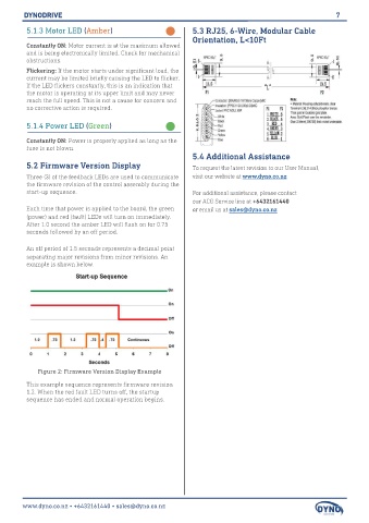
Each time that power is applied to the board, the green or email us at sales@dyno.co.nz
(power) and red (fault) LEDs will turn on immediately.
After 1.0 second the amber LED will flash on for 0.75
seconds followed by an off period.
An off period of 1.5 seconds represents a decimal point
separating major revisions from minor revisions. An
example is shown below.
Figure 2: Firmware Version Display Example
This example sequence represents firmware revision
1.2. When the red fault LED turns off, the startup
sequence has ended and normal operation begins.
www.dyno.co.nz • +6432161440 • sales@dyno.co.nz